(Stereoscopic Displays and Applications IV,
Proceedings of the SPIE Volume 1915, San Jose, CA, Feb. 1993.)
Image Distortions in Stereoscopic Video Systems
Andrew Woods 1
Tom Docherty 2
Rolf Koch 3
1,2
Centre for Marine Science & Technology,
Curtin University of Technology, G.P.O. Box U 1987, Perth W.A. 6845, AUSTRALIA.
3 School of Mathematical and Physical Sciences,
Murdoch University, South Street, Murdoch W.A. 6150, AUSTRALIA.
ABSTRACT
This paper discusses the origins, characteristics and effects of image distortions in stereoscopic video systems. The geometry of stereoscopic camera and display systems is presented first. This is followed by the analysis and diagrammatic presentation of various image distortions such as depth plane curvature, depth non-linearity, depth and size magnification, shear distortion and keystone distortion. The variation of system parameters is also analysed with the help of plots of image geometry to show their effects on image distortions.
The converged (toed-in) and parallel camera configurations are compared and the amount of vertical parallax induced by lens distortion and keystone distortion are discussed. The range of acceptable vertical parallax and the convergence/accommodation limitations on depth range are also discussed.
It is shown that a number of these distortions can be eliminated by the appropriate choice of camera and display system parameters. There are some image distortions, however, which cannot be avoided due to the nature of human vision and limitations of current stereoscopic video display techniques.
With the increasing use of stereoscopic video systems for teleoperation purposes, an understanding of the geometry and distortions of these displays is important to correctly use and configure such systems.
The geometry discussed in this paper has been developed for field-sequential stereoscopic camera and display systems such as the Curtin University Stereoscopic Video System1. The stereoscopic camera system consists of a pair of video cameras mounted side by side to obtain left and right images. The stereoscopic display system consists of a single display surface on which left and right images are displayed and separated by some coding method (time, color or polarisation). This discussion is applicable to other stereoscopic displays in which the stereoscopic image pair are displayed on the same display surface, however, it is not directly applicable to Head Mounted Display systems.
Stereoscopic video systems seek to display to an observer a true three-dimensional view of areal world scene. In the process of image acquisition and display, however, distortions can occur which can modify the observer's perception of the depicted scene or even reduce the quality of the stereoscopic image so that it is difficult to view.
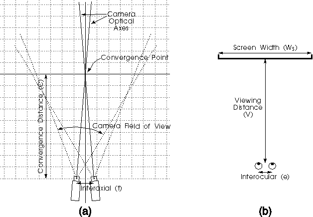
Figure 1: (a) Stereoscopic camera system and (b) stereoscopic display system
1.1 Stereoscopic video system configuration
Six basic parameters uniquely characterise a stereoscopic camera and display system. Figure 1 illustrates these parameters. The camera system configuration is determined by (a) the distance between the cameras, (b) the convergence distance (the distance away from the cameras at which the optical axes of the cameras intersect) and (c) the field of view of the cameras (determined by the CCD format size and the lens focal length).
The display system is determined by (a) the viewing distance of the observer from the display, (b) the size of the display (as measured by its horizontal width) and (c) the distance between the viewer's eyes.
In this discussion, the term `convergence distance' is simplified to mean the distance at which the optical axes of the two cameras intersect i.e. the distance at which the two camera images coincide in the centre of the stereoscopic display. This therefore includes the action of camera convergence by converging or toeing-in the cameras and also horizontal shifts of the CCD sensors or alternatively shifts of the images displayed on the monitor. It should be noted that shifts of the CCDs is preferred to shifts of the images at the display because the latter will result in blank bands on the sides of the image.
With reference to Figures 2 and 3, the following variables are used in the derivation of geometric models of stereoscopic acquisition and display:
t- Camera Separation. The distance between the first nodal points of the two camera lenses.
C- Convergence Distance. The distance from the convergence point to the midpoint between the first nodal points of the two camera lenses. C=t/ (2 tan[ ß + arctan( h / f )])
f- Lens Focal Length. The focal length of the two camera lenses.
Wc- CCD Width. The width of the camera imaging sensor. The horizontal width for the common 1/2 and 2/3 inch CCDs are 6.4 and 8.8mm respectively.
ß - Camera Convergence Angle. In the toed-in camera model, this is the angle the cameras are each rotated inwards from parallel to achieve convergence.
h- Sensor Axial Offset. In the parallel camera (with image shift) configuration, this is the distance by which the centre of each imaging sensor (CCD) has been moved away (outwards) from the optical axis of the lens to achieve convergence.
(alpha)- Camera Field of View. The horizontal angle of view of the camera.
(alpha) = arctan[(Wc/2+h )/ f ] + arctan[( Wc/2- h)/f ]
V- Viewing Distance. The distance from the observer's eyes to the display plane.
e- Eye Separation. The distance between the observer's eyes. Typically 65mm.
Ws- Screen Width. The horizontal size of the display screen.
P- Image Parallax. The horizontal distance between homologous points on the screen. P = Xsr - Xsl
M- Frame Magnification. The ratio of screen width (Ws) to camera sensor width (Wc). M = Ws / Wc
(Xo,Yo ,Zo ) - The location of a point in object space (in front of the cameras).
(Xi,Yi ,Zi ) - The location of a point in image space (as stereoscopically viewed by the observer when displayed on the screen).
(Xcl,Ycl ),(Xcr ,Ycr ) - The location of imaged points on the left and right imaging sensors respectively.
(Xsl,Ysl ),(Xsr ,Ysr ) - The location of left and right image points on the screen.
Ys- Screen Y coordinate of a fused stereoscopic image where vertical parallax is present. Ys =(Ysl +Ysr ) / 2
1.3 Geometry of stereoscopic video systems
The geometry of a stereoscopic video system can be determined by considering the imaging and display process as three separate coordinate transforms: Firstly from X,Y,Z coordinates in object/camera space to X and Y positions on the two camera imaging sensors (CCDs), secondly from the two sets of CCD coordinates to X and Y positions of the left and right images on the stereoscopic display, and thirdly to a set of X,Y,Z coordinates in image/viewer space.
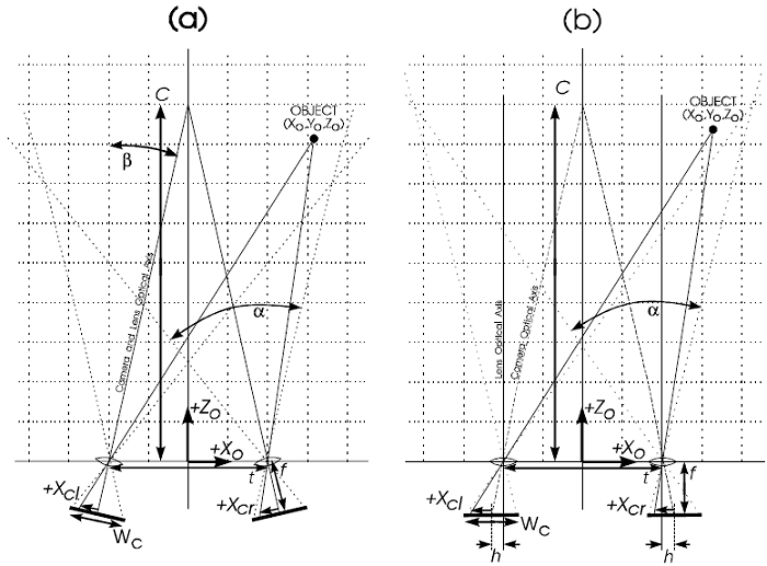
Figure 2: Camera parameters for (a) toed-in camera configuration and (b) parallel camera configuration (Plan View)
This is summarised as follows:
Object Space -> CCD Coordinates -> Screen Coordinates -> Image Space
 (Xo,Yo,Zo)  (Xcl,Ycl),(Xcr ,Ycr)  (Xsl,Ysl),(Xsr,Ysr)   (Xi,Yi,Zi)
The first coordinate transform is shown in equations (1) to (4). The variables and
coordinate conventions of this transform are shown in Figure 2 except for the Y axis
which for object space is centred at the midpoint between the first nodal
points of the camera lenses and positive in the upward direction and for CCD
coordinates is positive in the downwards direction from the centre of the CCD.
 .......(1)
 .......(2)
 .......(3)
 .......(4)
[An error in equations 3 and 4 was corrected 28 October 2004. The error did not occur in the pdf version of this paper.]
The transformation from CCD coordinates to screen coordinates is achieved by
multiplying by the screen magnification factor M:
Xsl = M Xcl .......(5)
Xsr = M Xcr .......(6)
Ysl = M Ycl .......(7)
Ysr = M Ycr .......(8)
The final transform from screen coordinates to image space coordinates is shown in
equations 9 to 11. The variables and coordinate conventions for this transform
are shown diagrammatically in Figure 3 except for the Y variables which are
positive in the upwards direction from the centre of the screen.
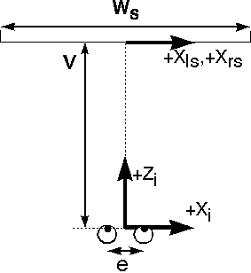
Figure 3: Viewing parameters (Plan View)
 .......(9)
 .......(10)
 .......(11)
Special
mention needs to be made about the Y coordinate equation. Two values can be
developed for the image space Y coordinate, one each from the left and right
views, Ysl and Ysr, however, only one Y position is meaningful.
Therefore a single value of screen Y position must be determined from these two
values. The difference between screen Y coordinates is termed `vertical
parallax' and determines how easily the stereoscopic image can be fused. If
vertical parallax is small we use Ys =(Ysl +Ysr )/2.
The overall coordinate transformation from object space coordinates to image space coordinates is:
 .......(12)
 .......(13)
 .......(14)
These
equations apply to both the parallel camera and the toed-in camera
configurations. Significant simplifications can be made for a parallel camera
configuration. It should also be noted that these equations do not contain any
small angle approximations. It has been found that small angle approximations
can obscure some stereoscopic distortions2,3.
1.4 Visualisation of stereoscopic video system geometry
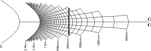
Figure 4: Coordinate transformation from Object Space to Image Space
(for C = 0.9m, f = 6.5mm, t = 75mm,
V = 0.9m, e = 65mm, Ws = 300mm).
In order to illustrate the results of the above equations, a computer program was
developed to generate plots which display the coordinate transformation from
object space to image space. An example of one of these plots is shown in
Figure 4. This plot shows the way in which the object space in front of the
camera system (in the XZ plane) is transformed to the display system (image
space). The grid pattern demonstrates how a rectilinear grid (of 10cm squares)
in front of the camera system has been distorted upon display. The two circles
represent the viewer's eyes and the bold line is the display. The grid pattern
extends to 3m away from the cameras. The curve furthest from the eyes
indicates where infinity from the cameras will be displayed on the monitor.
The grid pattern is not displayed past 3m to infinity due to its increasing
density.
1.5 Variation of parameters.
The manipulation of the three camera configuration parameters and the three display
configuration parameters are shown diagrammatically in Figures 5 and 6. These
figures show how the image display geometry of a predetermined camera and
display configuration is affected by changes of configuration parameters.
Click here for Picture (16k, 916 x 668)
Figure 5: Variation of camera configuration parameters
Click here for Picture (19k, 884 x 669)
Figure 6: Variation of display configuration parameters
2. STEREOSCOPIC DISTORTIONS
Stereoscopic
distortions are ways in which a stereoscopic image of a scene differs from
actually viewing the scene directly. There are a number of different types of
image distortions in stereoscopic video systems. This chapter will discuss
various types of image distortions including outlining their origins and their
effects on a viewer's perception of a scene.
2.1 Depth plane curvature
As
mentioned earlier, the same convergence distance can be achieved either by the
parallel camera configuration (with axial offset of the imaging sensor) or the
toed-in camera configuration (where the cameras are angled in). Figures 7(a)
and (b) show the same convergence distance achieved by first the toed-in camera
configuration and secondly by the parallel camera configuration. It can be
seen quite clearly from these plots that the toed-in camera configuration
results in a curvature of the depth planes. This will result in objects at the
corners of the image appearing further away from the viewer than objects at the
centre of the image. In contrast the parallel camera configuration results in
depth planes which are parallel to the surface of the monitor. Depth plane
curvature is closely linked with keystone distortion which is discussed later.
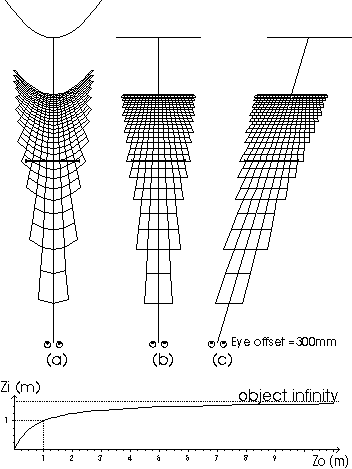
Figure 7: 3D maps of (a) toed-in cameras (b) parallel cameras (c) shear distortion and (d) plot of image distance versus object distance.
The depth plane curvature illustrated here could lead to wrongly perceived relative
object distances on the display and also disturbing image motions during
panning of the camera system.
2.2 Depth non-linearity
Figure 7(d) shows a plot illustrating the relationship between object distance away from
the camera system and image distance away from the eyes for the system configurations of Figures 7(a) and (b). The graph shows the convergence and viewing distances at 1m as dotted lines. It can be seen from this graph, Figure 7(d),and also the 3D maps of Figures 7(a) and (b) that the depth is stretched between the viewer and the monitor and compressed between the monitor and infinity.
The non-linearity of depth on the display can lead to wrongly perceived depth on the monitor and if the camera system is in motion it can lead to false estimations of velocity4. An example of this is the case of a stereoscopic camera system on a vehicle approaching a structure at a constant velocity. At first the vehicle will appear to be approaching the structure rather slowly but once the structure comes closer to the camera than the convergence distance, the vehicle will appear to accelerate. This could lead to incorrect actions in the control of the vehicle.
It has already been shown2,5 that a linear relationship between image depth and object depth can only be obtained by configuring the stereoscopic video system such that object infinity is displayed at image infinity on the stereoscopic display.
2.3 Shear distortion
A disadvantage of binocular stereoscopic displays is that the stereoscopic image appears to follow the observer when the observer changes viewing position.Change in the viewing distance has already been considered above. A sideways movement of the observer leads to a different type of distortion which we have called `shear distortion'. As can be seen in Figure 7(c), a sideways movement of the observer results in a sideways shear of the stereoscopic image about the surface of the monitor - images out of the monitor will appear to shear in the direction of the observer and images behind the surface of the monitor shear in the opposite direction.
Shear distortion can result in wrongly perceived relative object distances. In Figure 7(c),images on the left would falsely appear closer than images on the right.Another result of shear distortion (as well as a change in viewing distance) is that observer motion will lead to false perception of motion in the image. For example if the operator of a vehicle moved his head while the vehicle was stationary, image motion would be seen where the is none. This effect is most noticeable for images which are furthest away from the stereoscopic display surface.
2.4 Depth and size magnification
An analysis of image magnification or image scaling reveals that there can be a mismatch between depth magnification and size (width and height) magnification.This is particularly so when there is a non-linear relationship between image and object depth. A mismatch between depth and size magnification can lead to an image appearing flat or conversely stretched. We have not considered this effect in great detail in our research, however, an analysis of depth and size magnification is contained in references 2 and 5.
2.5 Keystone distortion
A well know effect of the toed-in camera configuration is keystone distortion.Keystone distortion causes vertical parallax in the stereoscopic image due to the imaging sensors of the two cameras being located in different planes. The effect of keystone distortion upon the display of a grid located at the camera convergence distance is shown in Figure 8. In one of the cameras, the image of the grid appears larger at one side than the other. In the other camera, this effect is reversed. This results in a vertical difference between homologous point which is called vertical parallax. The amount of vertical parallax is greatest in the corners of the image and increases with increased camera separation, decreased convergence distance and decreased focal length. In this example, a lens with a focal length of 3.5mm (C=1m and t=75mm) would exhibit vertical parallax of 8.2mm in the corner of the screen on a 16" diagonal monitor. It can also be seen from this diagram that horizontal parallax is also induced. This is the source of the depth plane curvature mentioned earlier. The parallel camera configuration does not exhibit keystone distortion.
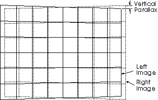
Figure 8: Vertical parallax caused by keystone distortion
2.6 Lens distortion
Lens radial distortion, often called pin-cushion or barrel distortion, is another source of image distortion and induced vertical parallax. Lens radial distortion is caused by the use of spherical lens elements, resulting in the lens having different focal lengths at various radial distances from the centre of the lens. Increasing focal length from the centre of the lens is called pin-cushion distortion and the reverse is called barrel distortion. Figure 9 shows the barrel distortion of a Canon 3.5mm lens mounted on a 1/2" CCD camera. The grid is an actual image from a camera and lens photographing a 5cm spaced grid located 320mm away from the lens. It can be seen from this figure that the curvature of the grid, especially in the corners of the image, can cause vertical parallax in the displayed image. Homologous points with increasing values of parallax will follow the horizontal lines on the grid. In the corners of the image the horizontal lines start to curve and therefore any image with horizontal image parallax will also exhibit some vertical parallax.The amount of vertical parallax displayed will depend upon the radial distance from the centre of the lens, the amount of horizontal parallax the image possesses and the properties of the lens. Our measurements have revealed that among common lenses, radial distortion is worst for short focal length lenses.Aspherical lenses are available which reduce the amount of radial distortion.These should be used where short focal length lenses are required and vertical parallax is seen to be a problem.
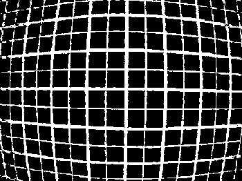
Figure 9: Lens radial distortion for 3.5mm lens
3. HUMAN FACTORS
In the previous sections various stereoscopic distortions have been characterised and their effects discussed. It is also important, however, to consider limits of the human visual system upon the perceived quality of stereoscopic images.This chapter will explore the visual limits of horizontal parallax and vertical parallax and how these limits affect image distortions.
3.1 Accommodation and vergence
A widely discussed limitation of field-sequential stereoscopic displays is the association between accommodation and vergence. In real world viewing,vergence and accommodation are normally closely linked visual actions, whereas stereoscopic displays require a different visual action. The eyes must remain focused at the surface of the screen at all times regardless of where the eyes are verged in the stereo monitor. It has been our experience that excessive screen parallax can lead to stereoscopic images appearing out of focus and/or the viewer being unable to fuse the images. We believe this to be due to the association between accommodation and vergence. Some research and recommendations have been published regarding the association between vergence and accommodation (refs 6,7,8).
In order to understand the limitations of the human visual system and gain some physical data, an experiment was conducted using the Curtin UniversityStereoscopic Video System (a 100Hz field-sequential stereoscopic display with a16" (diagonal) monitor and Tektronix polarising screen1). The experiment sought to measure people's limits of stereoscopic vision in and out of the stereoscopic monitor. This measures how far a subject's accommodation and vergence can be disassociated before image fusion of the stereoscopic image is lost. This in turn determines an individual's depth range, i.e. the range of image depths which can be successfully viewed stereoscopically.
3.1.1 Experimental method
The experiment was conducted by displaying a 4cm diameter donut on the screen with increasing or decreasing screen parallax. The increasing parallax measurements started by displaying the donut at the display surface and gradually increasing parallax in the crossed (out of the screen) or uncrossed (into the screen)directions until the observer lost fusion. The decreasing parallax measurements started by displaying the donut with crossed or uncrossed screen parallax equal to screen width and decreasing the screen parallax of the donut until the viewer could fuse the stereoscopic image. The experiment was conducted with ten subjects and each measurement was conducted at least three times. Viewers sat approximately 0.8m from the monitor.
3.1.2 Results
The results of the experiment are shown in Figure 10. The two outer curves show the point at which image fusion was lost for increasing crossed (negative) and uncrossed(positive) screen parallax. The two inner curves show the point at which image fusion was gained for decreasing crossed and uncrossed screen parallax. The data has been sorted in the vertical axis. The number above each data marker is the subject number. This allows the response of individual subjects to be determined from the graph. The horizontal axis shows the screen parallax value and also the image distance at which such an image would be perceived.
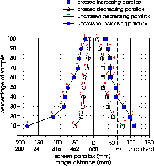
Figure 10: Experimental results of depth range limit
The results revealed a wide range of responses. Some of the subjects could only tolerate a small range of screen parallax, whereas others could perceive a large depth range. Some people could see more easily into the monitor than out of the monitor and others could more easily see out of the monitor than into the monitor. A few subjects could also diverge their eyes. The results also suggested that depth range improved with increased exposure to stereoscopic displays - subjects 9 and 10 had some previous experience with stereoscopic displays. The results could also reveal the ability of subjects to free-view stereo-pairs in the parallel-eyed (wall-eyed) or cross-eyed configurations.This requires disassociation of accommodation and vergence is different directions. We would expect subject 3 to be able to view parallel-eyed stereo-pairs and subject 10 to be able to view cross-eyed stereo-pairs.
These results indicate that in order for a stereoscopic image on a monitor to be viewed by as many people as possible, the depth range should be minimised. Obviously this directly opposes the requirements for a linear depth relationship and distortionless stereoscopic display mentioned earlier which require object infinity to be displayed at image infinity. Depending upon the range of depth at which objects of interest are located in object space (in front of the cameras), it may or may not be possible to display the image without distortions. If the scene has a large range of depths at which objects of interest are located in object space, it would be necessary to reduce the depth range at the screen and image distortions as shown in Figure 7 would result.These results also confirm that the primary area of interest (in the depth axis) should be located near the surface of the monitor (by the appropriate choice of convergence distance).
These results may not be suitable to determine a recommendation for the limitation of depth range. In this experiment, an arbitrary symbol was used as the fixation point. We have also noticed that the range of viewable parallax increases with increased viewing distance. We intend to repeat these experiments using real world (underwater) images and also different viewing distances. This should obtain results which are representative of real world use of stereoscopic video systems.
3.2 Vertical parallax
In the experiment above, visual limits of vertical parallax were also measured for increasing vertical parallax. The results indicated that homologous points should have less than 7mm of vertical parallax for image fusion to be possible.The subjects also reported that eye strain was apparent at higher values of vertical parallax. Needless to say, vertical parallax should be reduced as much as possible to produce an easily viewed image. "With the notable exception of glitter, sparkle, or lustre, the only desirable asymmetries in a stereoscopic system of photography and projection are the asymmetries of horizontal parallax." (ref 9)
4. DISCUSSION AND CONCLUSION
The main recommendation of this study is that the parallel camera configuration is used in preference to the toed-in (converged) camera configuration. This will eliminate keystone distortion and depth plane curvature. Comment should be made about the practicality of obtaining such an alignment. In the configuration of Figure 5 the difference between the alignment of the parallel & toed-in cameras configurations is 2.1° of rotation per camera and 0.24mm of axial offset relative to the lens per imaging sensor. Obviously such small differences need accurate means of alignment. Indeed, it has been our experience that off-the-shelf cameras do not provide sufficient control over CCD position relative to the lens. Some video cameras and lens combinations have so much freedom in their mounts that up to 2mm movement of the lens relative to the CCD is possible. If such a camera system was subject to vibration, the alignment of the system may be subject to continual change. In our experience, off-the-shelf cameras need to be modified to provide such control.
Lens radial distortion can be a significant source of vertical parallax,particularly when wide angle lenses are used on the camera system. When vertical parallax due to lens radial distortion is seen to be a problem, lenses with low radial distortion should be chosen. Aspherical lenses may meet this requirement.
As mentioned in Section 3.1, the association between accommodation and vergence places a limit upon the depth/parallax range of a stereoscopic image. This in turn means that a linear relationship between image and object distance may not be achievable. This will depend upon the depth content of the subject matter in front of the camera system and also the ability of the observers to whom the stereoscopic images are to be displayed. If the system is only to be used by trained observers, a larger depth range may be possible which will reduce depth non-linearity.
As mentioned earlier, the material in this paper was developed for afield-sequential stereoscopic video system. These principles are also directly applicable to other types of stereoscopic displays such as anaglyphic displays,polarised projected displays, half silvered mirror displays and some lenticular displays. These concepts are not directly applicable to head mounted displays,however, the techniques described could be adapted to head mounted display geometry.
It has been shown that there can be large range of distortions involved in the display of stereoscopic images on stereoscopic displays. It has also been shown that it is possible to eliminate some of these distortions by the appropriate choice of system parameters. There are some distortions, however, which cannot be avoided due to the nature of human vision and limitations of current stereoscopic video display techniques.
5. ACKNOWLEDGMENTS
The authors wish to thank Woodside Offshore Petroleum for their support of this project. We would also like to thank David Drascic for participating in many discussions during the process of this work.
6. REFERENCES
1. A. Woods, T. Docherty and R. Koch, "The use of Flicker-Free Television Productsfor Stereoscopic Displays and Applications," Stereoscopic Displays and Applications II, J. Merritt, S. Fisher, Editors, Proc. SPIE 1457, pp. 322-326, 1991.
2. D. Diner, "A New Definition of Orthostereopsis for 3-D Television," IEEE International Conference on Systems, Man and Cybernetics, pp. 1053-1058, October 1991.
3. R. Spottiswoode and N. Spottiswoode, The Theory of Stereoscopic Transmission and its Application to the Motion Picture, University of California Press, Berkeley, 1953.
4. D. Diner, "Danger of Collisions for Tele-Operated Navigation due to Erroneous Perceived Depth Accelerations in 3-D Television," Annual Meeting of the American Nuclear Society, 1991.
5. C. Smith, "3-D or not 3-D?" New Scientist, Vol.102 #1407, pp. 40-44, April 1984.
6. Y. Yeh and L. Silverstein, "Using Electronic Stereoscopic Color Displays: Limits of Fusion and Depth Discrimination," Three Dimensional Visualisation and Display Technologies, W. Robbins, S. Fisher, Editors, Proc. SPIE 1083, pp.196-204, 1989.
7. L. Hodges, "Basic Principles of Stereographic Software Development,"Stereoscopic Displays and Applications II, J. Merritt, S. Fisher, Editors, Proc. SPIE 1457, pp. 9-17, 1991.
8. R. Akka, "Automatic Software Control of Display Parameters for Stereoscopic Graphic Images," Stereoscopic Displays and Applications III, J. Merritt, S.Fisher, Proc. SPIE 1669, pp. 31-38, 1992.
9. L. Lipton, Foundations of the Stereoscopic Cinema, Van Nostrand Reinhold Company Inc., New York, 1982.
 The program which was used to generate the plots shown in Figures 4, 5, 6 and 7 is now available as shareware. Click here to download "3D-MAP". (Program runs under DOS on a 386 PC or higher) (47k, zip file)
Copyright on this document is retained by Curtin University. This document is not public domain. Permission is hereby given to reprint this paper on a non-profit basis for scholarly purposes provided the document is unaltered and this notice is intact. This paper may not be reprinted for profit or in an anthology without prior written permission. If you wish to reprint this paper on this basis, please contact the primary author at the address shown on the first page of this document.
This paper is also available as a pdf.
GO BACK to Andrew's Home Page
Last modified: 28th October, 2004.
Maintained by: Andrew Woods


 .......(1)
 .......(2)
 .......(3)
 .......(4)
 .......(9)
 .......(10)
 .......(11)
 .......(12)
 .......(13)
 .......(14)


![]() The program which was used to generate the plots shown in Figures 4, 5, 6 and 7 is now available as shareware. Click here to download "3D-MAP". (Program runs under DOS on a 386 PC or higher) (47k, zip file)
The program which was used to generate the plots shown in Figures 4, 5, 6 and 7 is now available as shareware. Click here to download "3D-MAP". (Program runs under DOS on a 386 PC or higher) (47k, zip file)